Monday, May 19, 2014

More chassis....and exhaust !

Couple of quick updates on the work connecting the front and rear chassis rails to the main floor section. All tied in together now.


Just to get some perspective to how tight the interior space is, temporarily set the Kirkey race we picked up into place.....and yes, did sit in it and make the requisite "vroom, vroom" noises.....

Quite evident that we'll need to do some work on relocating the current shifter location on the transmission in order to be able to row the gears properly.


Also did some work on modifying the factory S2000 exhaust header by chopping off the original section just past the four-to-two merge location. Given the low profile of the chassis, determined the best location to route the exhaust would be down the passenger side of the transmission tunnel, down the centre beside the driveshaft location, and out under the rear differential. The muffler will ultimately be located transversely behind the rear subframe with the tip out under the rear valance.


Started off by locating the new merge collector in the desired spot beside the transmission and proceeded to cut up some small sections of mandrel tube bends and straight tubing to get the desired shape we were looking for. Tack welded the parts together temporarily and will complete the finish welding on the bench.


Monday, May 12, 2014

Tube bender

Spent some time this weekend finishing up the build of the tube bender that we'll need once we get to the upper portions of the chassis, namely the roll cage and strut tower bars.

Finished cutting out all the material specified in the Trikes bender plans, and got to work welding the assembly together.


Mocked up the hydraulic/air ram to check for fitment and identified a tight spot on one of the inside tubes where the ram housing interfered with the pivot swing. Grabbed the grinder and proceeded to remove about 3/16" from the housing...pivots like a charm now. Also added some castor wheels to make it easier to move around....this thing is heavy !


Added some paint for rust protection. Next we'll add the new tube die and give it a test run when the steel tubing order arrives.


Monday, April 21, 2014

Back to chassis....

In one of the previous posts we completed building out the tubing structure that will become the main floor section of the chassis.

In this post, we started by mocking up this completed tubing structure into the body, clamping it in multiple locations to ensure that it was aligned and leveled in the proper location using the rear S2000 subframe mounts as reference, which we also located into the new crossmember to serve as subframe mounting pads.

Applied a few short tack welds in each corner to ensure nothing moved, and then proceeded to stitch weld the new floor section to the inner rocker panels that we fabricated and installed earlier into the body structure.


Next, we re-installed the transmission, and set it to proper height with temporary piece of plate steel at the rear in order to check the clearance down the floor section where the transmission tunnel will be located.


Encountered some minor interference from an extraneous tab on transmission, which we proceeded to grind off. We will eventually need to take a small scallop out of the frame tube in the same location for additional clearance, but overall, the transmission fits very well. 


Dummied up a short piece of exhaust tubing of appropriate diameter to simulate the driveshaft location....looking good for clearance over the floor section.


In the next post we'll be working on connecting the new floor section to both the front and rear rails we fabricated earlier.

Monday, April 7, 2014

Tools...everyone loves Tools !!

The weather this year has been crazy, seems like the snow and winter will never end !

So rather than bring the Mini back inside the shop to continue on the chassis work, decided to start work on building the tube bender that will eventually be needed to construct the majority of roll cage and upper chassis assemblies.

I had some previous experience building a 6 point roll bar setup for my Camaro build a few years back, (https://www.flickr.com/photos/spetroff/sets/72157632420243515/) but farmed out all of the bending for that project. Given the shear number of tubes and bends that will be needed on this Mini build, decided that constructing the roll cage in house this time was the better way to go.

Did some research a while back on what tube benders are available in the marketplace at a reasonable price point. Looked at the JD Squared, Pro Tools, etc. and discovered a number of people were having great success building their own benders using a set of plans from Got Trikes. Liked the fact that it utilized simple construction techniques, readily available materials, and used the Pro Tools Model 105 tube dies. Also, the design allowed for the addition of air/hydraulic assist ram to reduce the muscle power required as with other standard tube benders.

http://www.gottrikes.com/Tube_Bender.htm

Given the majority of the roll cage tubing we will be using is 1.5" DOM, I also picked up a new Pro Tools 1.5"OD x 4.5"CLR x 240 Degree Die Set from a local off-road vehicle parts manufacturer, TMR Customs. They were very helpful, and were familiar with the bender design that I chose and had good things to say about it. Great bunch of guys.

http://www.tmrcustoms.com/store/

While researching the benders, I also discovered that a number of people had praised the use of tube bending design software from a company called Bend-Tech. Given the fact that the layout of all the roll cage tubing required will be all custom designed, figured that this software would pay for itself in time savings and wasted dollars in expensive tube bending mistakes. Ended up purchasing the Bend-Tech EZ 3D and played around with it for an hour or so, and I must say it's super easy to use and comes with a large number of built in pre-defined templates that you simply plug your own measurements into.

http://www.bend-tech.com/

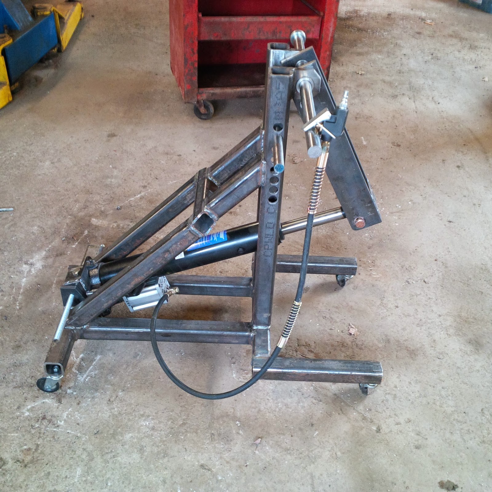
Picked up some plate and square tube steel, some hardened shaft and got started. Made some progress with building out a few of the sub assemblies of the bender. More to come.....


Sunday, March 23, 2014

Chassis continued.....

Got busy welding up the tubing, using the fixture we created in the previous post to keep all of the tubes located correctly. Started by going around the outside perimeter with series of tack welds in order to help minimize distortion, then allowing it to cool, and then worked on tacking the inner tubes.

After tacking up two complete sub assemblies (left and right), mocked them up against the rear cross-member and proceeded to weld the entire assembly together.


Tacked a short piece of tubing temporarily across the front to maintain square while going back over the entire assembly with finish welds.


 Once the welds cooled down, took some of the higher weld beads down with the grinder and then proceeded to use a flap disk to finish up the joints.


Sunday, March 9, 2014

More chassis fabrication

Took the plans that my brother drafted up in AutoCAD, and printed out via plotter in 1:1 scale, and taped them down to a sheet of 3/4" plywood. The design was laid out so that each side of the floor was the same, allowing space for the centre transmission tunnel, which allowed the same fixture to be used for both sides, essentially flipping one of the completed sections over and linking them together with additional substructure for centre tunnel. 

 
Proceeded to rip some additional 3/4" plywood into 3" strips that were then screwed around the inside and outside perimeter of the drawing points where tubes will be laid.

Using the measurements from the drawing, fired up the bandsaw and got started cutting tubing, and laid them out in the fixture one by one, making sure the joints are tight with optimal gaps for welding.


Once the first complete set of tubes were constructed, started with the second set for the opposite side.


Two complete sets of tubes, ready to be welded up.


Saturday, February 15, 2014

More chassis work....

Moved up front to start work on laying out the tubes to connect the front subframe.

First item on the agenda is to build out a fixture or jig that uses the front frame sections from the Honda S2000 I obtained previously as reference points. This fixture will then be used to locate the upper control arm and strut mounting points which will then be transferred onto the new tubing members when we get to that point.


Next, laid out the mounting points for the S2000 front subframe onto the new tubing rails, milled out the holes, and then tack welded the threaded bosses in for the mount bolts.


Also spent some time figuring out the mid section of the chassis layout. Captured the dimensions required and had my brother draft the layout in AutoCAD.  He was able to print out the rendering to full size using his plotter which will be great when it comes to laying out the tubing. Will share this with the next post......